Page 3 of 4 FirstFirst 1234 LastLast
Results 81 to 120 of 146

Thread: Not quite a rebirth after all...

  1. #81
    Forum Member yankeerob's Avatar
    Join Date
    May 2007
    Location
    Amongst the Pennine mills...
    Posts
    1,323

    Re: Not quite a rebirth after all...

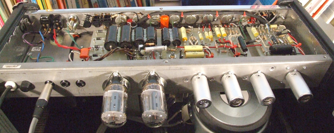
    It's gonna be a 5F6A with the PS from the HRDv and the bias circuit as gratefully provided by JAM - there's also a little twist in the tale as I've, despite all the protestation, obtained a 12AT7 driven send/return circuit that I can either use for my outboard FX, as an extra gain stage or bypass altogether. As the 12AT7 only draws 10mA and I've screened all the inputs and outputs it shouldn't be a problem and I've used all 1 and 2W resistors and higher voltage rated caps throughout to hopefully get a level of reliability and better heat dissipation. I've had to drill another hole for the extra tube in between V2 & V3 (with the S/R 12AT7 where V1 was) but I'm using aluminum shrouded tube sockets from TAD with gold plated pin sockets - a bit pricey but what the hey... Should be enough screening and heat shouldn't be that much of an issue...

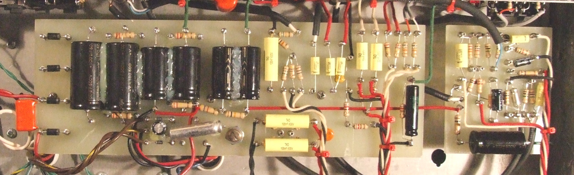
    The reason for moving the iron slightly is purely so the PT primaries are nearer the switches and the secondaries are nearer the board - just made sense - likewise with the OT. I've kept them reasonably apart - well - no nearer to each other or anything else than they were... I've put all the linking on the back side of the board (which I may live to regret but there you are) to keep it components only on the service side but the turrets seem to be happy with that arrangement. I'd originally drilled out a piece of oak to do all the turret staking but it proved to be too green and soft so I resorted to manufacturing a staking tool out of a disused standoff and an old centerpunch - it did the job very well in the end!

    Pics to be published soon and hopefully some sound bites by the end of next week or so - my mate John's back at the weekend so we'll be able to test it and fire it up early next week - sorry for the wait - hopefully it'll be worth it!

  2. #82
    Forum Member stevo's Avatar
    Join Date
    Mar 2005
    Location
    Germany
    Posts
    34

    Re: Not quite a rebirth after all...

    Hi Rob -

    do you have a larger/clearer version of the schematic you're using? My old eyes just can't read the one you linked to.

    Or is it the Deville PSU w/no changes + 5f6 circuitry (dvl ot of course) and JAM's bias circuit? If the values in the PSU are identical to those in the original dvl circuit, ok; I just can't see it clearly enough to see if anything has been changed.

    I was getting close to selling my dvl, I'm really eager to hear how this works out for you.


    thx

    steven

  3. #83
    Forum Member yankeerob's Avatar
    Join Date
    May 2007
    Location
    Amongst the Pennine mills...
    Posts
    1,323

    Re: Not quite a rebirth after all...

    Yer - no probs - I've only got an A4 printer so I've wound up whipping a few resistors out here and there where I've put the wrong ones in due to misreading the layout!!!

    Here's the schematic - http://images.lilypix.com/albums/use...A-Dv_schem.jpg

    I'm working on removing the S/R by hand from the layout in Photoshop - pump that up in a minute or two (or three....)

    :

  4. #84
    Forum Member stevo's Avatar
    Join Date
    Mar 2005
    Location
    Germany
    Posts
    34

    Re: Not quite a rebirth after all...

    Thanks, that's much better.

    steven

  5. #85
    Forum Member yankeerob's Avatar
    Join Date
    May 2007
    Location
    Amongst the Pennine mills...
    Posts
    1,323

    Re: Not quite a rebirth after all...

    Here's the layout - you'll notice I've removed two of the four inputs so there are just 1 normal and 1 bright input - I've added a bridging switch to see what it does but may remove it - I didn't see the point of four inputs as I'd never use them in practice - the S/R just goes in between the wiper on the treble pot and the 22uF cap - not sure how that'll work to be honest but I've had some of the best amp-heads in Yorkshire looking at this thing all along as well as the guys in the forum - again - many thanks to you all - any way here's the link for the layout...

    http://images.lilypix.com/albums/use..._layout_A3.jpg

    Oh - and BTW - you'll notice the tubes have all been shifted over to accomodate the 12AT7 for the S/R - I think this will actually work as there are gain controls on both the send and return as well as a switchable -20dB pad on the send though it won't be necessary with the TC Electronics G# cause it's also got very forgiving input and output attenuation - if it doesn't work it'll be no big deal to just whip it back out and you guys can say I told you so!!!

    Spk soon

  6. #86
    Forum Member yankeerob's Avatar
    Join Date
    May 2007
    Location
    Amongst the Pennine mills...
    Posts
    1,323

    Re: Not quite a rebirth after all...

    Spotted another little error - the bridging switch will have to be DPTP so when the channels are bridged the earth will be removed from the switches on the jack sockets but the 1M resistors will remain between earth and tip... details... always the details...

  7. #87
    Forum Member yankeerob's Avatar
    Join Date
    May 2007
    Location
    Amongst the Pennine mills...
    Posts
    1,323

    Re: Not quite a rebirth after all...

    OK, guys - fired her up this afternoon and spotted a few dumbass errors and sorted them out (including plugging the leads into my DMM the wrong way around!! : ) but have a problem with the bias - I have a healthy 440 or so on the plates but I'm measuring -20V at the lowest setting on the pot - so presumably this a simple matter of swapping the resistors out in the bias supply circuit?

    To refresh memories - here's the bias circuit as is -


    It was about -62V in the middle of the pot though it may not have been exactly in the middle and like a dumbass I've slipped with the MM probe and taken out the only 2A fuse I've got til tomorrow so I can't measure the highest point now double : - but we're close - so very close....

  8. #88
    Forum Member NTBluesGuitar's Avatar
    Join Date
    Apr 2006
    Location
    North Texas
    Posts
    5,820

    Re: Not quite a rebirth after all...

    Looks like that 25K could be dropped some, but only if you need to. I had to drop the HRDlx-bias circuit resistor from 100K to 33K to get in the range I wanted.

    But you're dealing with 440vdc as Fezz says, Mine was only 380-390 on the plates.

    Oh, I'm using the 1ohm off the cathode method as well.
    "...pray do not imagine that those who make the noise are the only inhabitants of the field;
    that, of course, they are many in number; or that, after all, they are other than the little,
    shriveled, meagre, hopping, though loud and troublesome, insects of the hour."

    -Edmund Burke

  9. #89
    Forum Member yankeerob's Avatar
    Join Date
    May 2007
    Location
    Amongst the Pennine mills...
    Posts
    1,323

    Re: Not quite a rebirth after all...

    I've got something wrong as the tubes are red lining - I've kept an eye on it and put it back into standby before they've run for too long but the rest of the voltages look OK - it's possible the tubes are shagged as they're an old pair I've thrown in for test purposes but I seem to remember them being OK...

    As I'm a complete plank of a newbie I'm not entirely sure what you mean by 1 ohm off the cathode - I know what the cathode is but have no way of measuring mA with what I have here - John's away til tomorrow but I've arranged to see him tomorrow as he's totally kitted out to do this stuff properly - besides that I have to get a bag o' 2A fuses - can't remember if they're fast or slow blow either...

    But thanks to everyone - I'm totally chuffed we've gotten this far and I've got so pics to edit and post up - so they'll be up later tonight sometime...

  10. #90
    Forum Member NTBluesGuitar's Avatar
    Join Date
    Apr 2006
    Location
    North Texas
    Posts
    5,820

    Re: Not quite a rebirth after all...

    Basically, the way the Hot Rod amps are set up is that the power tubes' cathodes are wired together and then to ground. But, right before that path gets to ground, you put in the 1ohm resistor.

    You measure at the 1ohm resistor (on the cathode side, not the ground side) to get the mV readings; which, in this case is for BOTH TUBES TOGETHER.

    *edit*
    Doh! Fezz beat me to it.
    "...pray do not imagine that those who make the noise are the only inhabitants of the field;
    that, of course, they are many in number; or that, after all, they are other than the little,
    shriveled, meagre, hopping, though loud and troublesome, insects of the hour."

    -Edmund Burke

  11. #91
    Forum Member yankeerob's Avatar
    Join Date
    May 2007
    Location
    Amongst the Pennine mills...
    Posts
    1,323

    Re: Not quite a rebirth after all...

    Hey guys - thanks big time - when I get some fuses tomorrow I'll get to and report in

  12. #92
    Forum Member yankeerob's Avatar
    Join Date
    May 2007
    Location
    Amongst the Pennine mills...
    Posts
    1,323

    Re: Not quite a rebirth after all...

    : : :

    It'd help if I'd have crossed the drawings a bit better and put in the earth resistor and diode as per the HRDv drawing - which might just have something to do with the red lining... just goes to show a little knowledge can be a dangerous thing - have always been a great fan of T Edison though!!!

  13. #93
    Forum Member
    Join Date
    Jul 2005
    Location
    So Calif
    Posts
    3,321

    Re: Not quite a rebirth after all...

    YR,

    You didnt catch my revised bias circuit, I posted it back aways. The revision should give more range.

    http://members.canonphotogroup.com/joem/HRDv%20Bias.jpg

    This is more like a traditional Fender bias circuit, and except for the values is the same I'm using in my Weber kit

  14. #94
    Forum Member NTBluesGuitar's Avatar
    Join Date
    Apr 2006
    Location
    North Texas
    Posts
    5,820

    Re: Not quite a rebirth after all...

    Oh, I'm pretty sure you can leave off the diode, too, Rob. It didn't affect how the readings worked out for me. Just get that 1 ohm to ground in there.
    "...pray do not imagine that those who make the noise are the only inhabitants of the field;
    that, of course, they are many in number; or that, after all, they are other than the little,
    shriveled, meagre, hopping, though loud and troublesome, insects of the hour."

    -Edmund Burke

  15. #95
    Forum Member yankeerob's Avatar
    Join Date
    May 2007
    Location
    Amongst the Pennine mills...
    Posts
    1,323

    Re: Not quite a rebirth after all...

    Cheers guys - thanks for pointing that out JAM - I think I've got a 100uF electrolytic - if not I'll grab one in the morning with the fuses - in the mean time here's some pics


  16. #96
    Forum Member yankeerob's Avatar
    Join Date
    May 2007
    Location
    Amongst the Pennine mills...
    Posts
    1,323

    Re: Not quite a rebirth after all...

    Another quick question - I'm using 1N4007's in the bias circuit - they're rated at 1Kv 1A - that's plenty there; right? See ya'll tomorrow

  17. #97
    Forum Member ziess's Avatar
    Join Date
    Oct 2005
    Location
    Sunny Falkirk, Scotland.
    Posts
    2,698

    Re: Not quite a rebirth after all...

    Looking good man!

    What's the separate board on the right of the chassis? And this is a 5F6A, right?
    4 preamp tubes?

    Tommy.

  18. #98
    Forum Member
    Join Date
    Jul 2005
    Location
    So Calif
    Posts
    3,321

    Re: Not quite a rebirth after all...

    Nice work, looks great! One thing nice about using the HRDx chassis; it's nice and roomy in there. I've got a start on my Weber, and the tweed chassis are a little tight.

  19. #99
    Forum Member NTBluesGuitar's Avatar
    Join Date
    Apr 2006
    Location
    North Texas
    Posts
    5,820

    Re: Not quite a rebirth after all...

    Damn fine work, sir!

    Tommy, I think rob worked in the FX loop, footswitching, or something using the extra tube...is that right, Rob? Did you get that red-plating issue worked out?

    Most importantly, how does it sound?
    Last edited by NTBluesGuitar; 10-05-2007 at 06:40 PM.
    "...pray do not imagine that those who make the noise are the only inhabitants of the field;
    that, of course, they are many in number; or that, after all, they are other than the little,
    shriveled, meagre, hopping, though loud and troublesome, insects of the hour."

    -Edmund Burke

  20. #100
    Forum Member
    Join Date
    Aug 2007
    Posts
    5,201

    Re: Not quite a rebirth after all...

    Man, that looks clean!
    "I haven't slept for ten days...because that would be too long." -- Mitch Hedberg

  21. #101
    Forum Member yankeerob's Avatar
    Join Date
    May 2007
    Location
    Amongst the Pennine mills...
    Posts
    1,323

    Re: Not quite a rebirth after all...

    Thanks guys - TJ's pics were an inspiration and I'd had some experience building hi-spec PTP PSU's for a company that manufactured hi-end medical stuff when you could still get that kind of work... the QA guys were pretty fussy! I have to say it didn't take long to populate the boards but took ages to do the rest...

    The board on the right is a 12AT7 S/R (though I've got a GE 5751 to try in there as well) that'll be easy enough to ditch if it doesn't work/sounds crap... It can be used as an extra gain stage/MV as well...

    I'm off to the trade counter now to get some caps to swap out the 47uF for a 100uF as per JAM's revised bias circuit, some 1 ohm resistors and some fuses... will be later before I can get to it as the 's got the whip out this morning - seems she'd like to have her dining room back sometime this weekend

  22. #102
    Forum Member NTBluesGuitar's Avatar
    Join Date
    Apr 2006
    Location
    North Texas
    Posts
    5,820

    Re: Not quite a rebirth after all...

    You're saying that board is a Send/Receive? Cool. If that works out for you, I'd LOVE that schematic you used.

    Not sure if I could have a use for it, but it would be worth studying.

    This is pretty cool stuff.
    "...pray do not imagine that those who make the noise are the only inhabitants of the field;
    that, of course, they are many in number; or that, after all, they are other than the little,
    shriveled, meagre, hopping, though loud and troublesome, insects of the hour."

    -Edmund Burke

  23. #103
    Forum Member yankeerob's Avatar
    Join Date
    May 2007
    Location
    Amongst the Pennine mills...
    Posts
    1,323

    Re: Not quite a rebirth after all...

    OK - here's where we're up to - I swapped out the 47uF for a 100uF in the bias circuit and put the 1 ohm resistor between the cathodes and ground (it was just going to ground previous - my error) - I got 3W wirewound silicone ones as they were the beefiest I cound get without ordering something special - thought they'd be man enough for the job - I've gone through everything and it's all as per the schematic/layout...

    Swapped out the TAD pre-amp tube sockets for Edicron ones - the TAD ones are garbage - I know you Stateside guys wouldn't bother with ordering straight from TAD unless they had something really special that you wanted but a warning to anyone in Europe... The TAD tube sockets are CRAP! Gold plated? They may as well be mold plated for what good they are - really cheap & nasty - Fortunately I ordered some Edicron ones from Rapid (as I didn't like the look of the TAD ones when they arrived - should have gone on first impressions and just sent them back but I'll have to live and learn on this one...) the Edicron's are pretty good - gold plated with ceramic bases though I had to superglue the ceramic to the inner metal work as the holes in the Dv chassis are so big it'd wobble a bit otherwise - if you were doing a chassis from scratch they'd be fine as long as you drill the right size holes...

    To the particulars - I have a plate voltage of around 454-5 - there's quite a difference between what my meter reads on autosense and when you set it specifically to measure DC and adjust the range - hence the difference - I'm getting a range of about -15 to -28.5 now on pin 5 and about 280mV on the cathodes... I don't leave it on for long as although I've thrown the old GT's in there to test it - they still work AFAIK...

    Also - I have quite a drop in voltage between points C & D - from about 372-3 to 240 - here's the links to the scematic and layout

    scematic - http://images.lilypix.com/albums/use...A-Dv_schem.jpg

    layout - http://images.lilypix.com/albums/use...-FX_layout.jpg

    I've been asked not to publish the scematic for the S/R but I've left it in the layout so you might have a clue - is it possible that's dragging the voltage down at point D?

    So anyway - there you have it - haven't plugged anything into it as it's obviously not quite there yet - don't know if I've damaged anything so far but I haven't smelled anything burning

    edit - I haven't changed the value on the 47uF cap in the bias circuit yet...

  24. #104
    Forum Member NTBluesGuitar's Avatar
    Join Date
    Apr 2006
    Location
    North Texas
    Posts
    5,820

    Re: Not quite a rebirth after all...

    Are those JFETs next to the send/receive pots? No...wait, those are your In/Out jacks. My bad...forgot you are using the Neutrik style jacks.

    Groovy.

    Oh, forgot to say that you might look into the availability of Belton tube sockets. Not sure if you can get then at a good price, but they're the bees knees.
    "...pray do not imagine that those who make the noise are the only inhabitants of the field;
    that, of course, they are many in number; or that, after all, they are other than the little,
    shriveled, meagre, hopping, though loud and troublesome, insects of the hour."

    -Edmund Burke

  25. #105
    Forum Member yankeerob's Avatar
    Join Date
    May 2007
    Location
    Amongst the Pennine mills...
    Posts
    1,323

    Re: Not quite a rebirth after all...

    Quote Originally Posted by NTBluesGuitar View Post
    Oh, forgot to say that you might look into the availability of Belton tube sockets. Not sure if you can get then at a good price, but they're the bees knees.
    Yer - Edicron is a company that sources and badges pretty good stuff - just had a look on the tubedepot site - they have some pics of the Belton sockets - guess what? That's what I've got - the gold plated ceramic based ones - yer - nice shout - they are rather sexy!!! I haven't done the power tubes yet as the TAD ones seem to be working OK for now but I got some Beltons just in case - The TAD's wouldn't stand the test of time in the power tube dept. as they're obviously made of too thin a gauge of whatever it is under the gold plating - I'm really disappointed with TAD in general as some of their stuff is OK but I'm starting to find a lot of it is cheap and nasty - will swap 'em out once I've got it working - I'm thinking of whipping the S/R out to see if that makes a significant change... and that choke is weeny - the 022707 is what they put in DR's - I'd thought when I was building it that I'd probably wind up upgrading it if I didn't burn the danged thing out first!!!

    If you have a look at the layout you'll see that the S/R takes it's power after the anodes on V2 (disregarding the S/R's 12AT7) - and I'm wondering if it's the S/R circuit that's dropping the voltage... anyway - the 's made a big roast dinner and all she's seen is the back of me bent over the dining room table with flux smoke wafting up for days so I'm gonna pay her a bit of attnetion tonight - if anyone has any thoughts feel free to express them - thanks again to everyone!!
    Last edited by yankeerob; 10-07-2007 at 09:58 AM.

  26. #106
    Forum Member yankeerob's Avatar
    Join Date
    May 2007
    Location
    Amongst the Pennine mills...
    Posts
    1,323

    Re: Not quite a rebirth after all...

    Right - I think putting both the B+ and OT CT before the choke is a probably a good idea - do I need any resistors or caps in there or do I just parallel them before the choke? Also I'm going to temporarily take the S/R completely out of circuit to see what happens as well...
    I'll be checking the thread now and again tonite and having another stab at it tomorrow

  27. #107
    Forum Member NTBluesGuitar's Avatar
    Join Date
    Apr 2006
    Location
    North Texas
    Posts
    5,820

    Re: Not quite a rebirth after all...

    I put the OT CT at the first stage filter cap where the B+ connection comes in from the rectifier (or standby switch), along with the first choke connection.

    The second stage filter cap has the other side of the choke, and the connection from pins 4 of the power tubes.

    I put the power tubes after the choke, and the OT CT before the choke. Nothing extra...just moved the OT CT from being after the choke as the tweeds did, and that was because the chokes are so tiny in these Hot Rods.

    Of course, you have some caps in series in your filter stages, but I'm sure you can find those points.
    "...pray do not imagine that those who make the noise are the only inhabitants of the field;
    that, of course, they are many in number; or that, after all, they are other than the little,
    shriveled, meagre, hopping, though loud and troublesome, insects of the hour."

    -Edmund Burke

  28. #108
    Forum Member
    Join Date
    Jul 2005
    Location
    So Calif
    Posts
    3,321

    Re: Not quite a rebirth after all...

    Quote Originally Posted by yankeerob View Post
    Right - I think putting both the B+ and OT CT before the choke is a probably a good idea...
    Yeah, otherwise you'll need a choke for the higher current. For example, my 5E7M came with a Weber W014684 choke, which is nearly as large as the OT. I'm building the amp closer to a 5F6A (I call it a 5F7) and am using the same choke as a SR/ DR type. (22699). The choke is after the OT CT just before the screens like most later (not 5E7/5E5/5F4) Fenders.

    If the bias voltage is low and you did change to the revised bias circuit, reduce the 18K resistor.

    You can see how much larger the choke for the earlier Tweeds is here.
    Last edited by JAM; 10-07-2007 at 12:11 PM.

  29. #109
    Forum Member yankeerob's Avatar
    Join Date
    May 2007
    Location
    Amongst the Pennine mills...
    Posts
    1,323

    Re: Not quite a rebirth after all...

    Firstly - for the sake of simplicity I'm going to refer to the two 100uF's as the first filter cap and the two 47uF's as the second - also am I right in thinking that connecting to either of these points would have the same result electrically? Am I right in thinking it's simply two parallel circuits (cap & resistor) wired in series or is it important to connect to the right hand arrow instead of the left?


    Just so you all can see what I'm talking about -


    Before I change the 18K resistor in the bias circuit I think it'd be prudent to take the S/R out of circuit - I strongly suspect that it's robbing the voltage once we get past the 10K resistor between points C & D (drops from about 372 to 240) - a 10K resistor on it's own shouldn't be dropping the voltage by over 130V; should it? My thinking is - I've got the S/R taking it's power from where point D feeds those two 100K resistors and the first anode on V2 etc... It's my guess that if I disconnect the power rail to the S/R at that point we should see a difference in voltage at point D and it might follow back through the circuit...

    Also are you saying to connect the OT CT to point A and pin 4 to where the choke returns and goes into the second filter cap (first 47uF 500V)?

    Once we get this thing somewhere in the ballpark we'll think about where to take the power for the S/R from - if that's even an option - also I've got to check what the S/R should be drawing and also check I haven't made any dumbass mistakes in translating the schemo to a layout...

    I gotta thank you guys again - I'm learning a hell of a lot - and am looking forward to building a smaller, simpler amp from scratch after this as well as a 100W head - spk soon!!

  30. #110
    Forum Member
    Join Date
    Jul 2005
    Location
    So Calif
    Posts
    3,321

    Re: Not quite a rebirth after all...

    Firstly - for the sake of simplicity I'm going to refer to the two 100uF's as the first filter cap and the two 47uF's as the second - also am I right in thinking that connecting to either of these points would have the same result electrically?
    Yeah, it's the same point.

    Also are you saying to connect the OT CT to point A and pin 4 to where the choke returns and goes into the second filter cap (first 47uF 500V)?
    Yep, just like the HRDx has it in the schematic you posted. (actually point "Z" goes to a 470 ohm resistor then pin 4)

  31. #111
    Forum Member yankeerob's Avatar
    Join Date
    May 2007
    Location
    Amongst the Pennine mills...
    Posts
    1,323

    Re: Not quite a rebirth after all...

    Okey dokey - I have got 470Ω's in there (2 1K 1W's in parallel) as done the classic anchored between pins 6 and 4 fashion, wire soldered to the 6 pin - thanks for answering that first dumbass question - it just looked awkward to me the way it's drawn on the Fender schemo and even more awkward when you try to lay it out in a compact yet serviceable way...
    Last edited by yankeerob; 10-08-2007 at 01:24 AM.

  32. #112
    Forum Member yankeerob's Avatar
    Join Date
    May 2007
    Location
    Amongst the Pennine mills...
    Posts
    1,323

    Re: Not quite a rebirth after all...

    Another quickie - I have both pin 8's going to a single 1 ohm 3W resistor to ground - should I have one on each pin 8 then to ground?

    I know these are annoying questions but I've seen this on other designs and wonder if this would be better...

    Thanks... again

  33. #113
    Forum Member NTBluesGuitar's Avatar
    Join Date
    Apr 2006
    Location
    North Texas
    Posts
    5,820

    Re: Not quite a rebirth after all...

    Hot Rod's bias is set up like you have it now; both tubes to the 1ohm.

    You just adjust your math to consider that the reading is from both tubes. But you can run them to their own dedicated 1ohm as well to get individual tubes' readings.
    "...pray do not imagine that those who make the noise are the only inhabitants of the field;
    that, of course, they are many in number; or that, after all, they are other than the little,
    shriveled, meagre, hopping, though loud and troublesome, insects of the hour."

    -Edmund Burke

  34. #114
    Forum Member yankeerob's Avatar
    Join Date
    May 2007
    Location
    Amongst the Pennine mills...
    Posts
    1,323

    Re: Not quite a rebirth after all...

    Gotcha - presumably this would also allow me to know if one was drawing more than the other? Cool - I'll be getting the iron out later... we should have some results before the sun sets in N Texas!

  35. #115
    Forum Member NTBluesGuitar's Avatar
    Join Date
    Apr 2006
    Location
    North Texas
    Posts
    5,820

    Re: Not quite a rebirth after all...

    Well, it just rose about 2 hours ago...so you have time.
    "...pray do not imagine that those who make the noise are the only inhabitants of the field;
    that, of course, they are many in number; or that, after all, they are other than the little,
    shriveled, meagre, hopping, though loud and troublesome, insects of the hour."

    -Edmund Burke

  36. #116
    Forum Member
    Join Date
    Jul 2005
    Location
    So Calif
    Posts
    3,321

    Re: Not quite a rebirth after all...

    Quote Originally Posted by yankeerob View Post
    Gotcha - presumably this would also allow me to know if one was drawing more than the other?
    Exactly, that way you can tell how well matched the output tubes are.

  37. #117
    Forum Member yankeerob's Avatar
    Join Date
    May 2007
    Location
    Amongst the Pennine mills...
    Posts
    1,323

    Re: Not quite a rebirth after all...

    OK - here's where we're up to - hiatus hernia's gone down - soldering iron is fired up - S/R's completely removed - OT CT is at very beginning of smoothing chain - screens are just before the choke - 1Ω resistors in place between both pin 8's and ground - 18K resistor is swapped out for a 5K6 and I'm getting -35V now instead of -28 at the control grid - how much lower should I drop this? Thanks again guys!! I'm also getting an extremely high voltage at pin 4 - like about 504V but Have taken the power tubes out until I get this a bit closer - is that normal?
    Last edited by yankeerob; 10-09-2007 at 03:40 PM.

  38. #118
    Forum Member yankeerob's Avatar
    Join Date
    May 2007
    Location
    Amongst the Pennine mills...
    Posts
    1,323

    Re: Not quite a rebirth after all...

    What just keep trying until we get what we're looking for? Is there a point where the value will be too low? Does there need to be at least some resistance in there? I suppose that's what I'm asking - thanks Fezz!! I'm all for T. Edison and all but I don't fancy setting the caboose on fire...

  39. #119
    Forum Member yankeerob's Avatar
    Join Date
    May 2007
    Location
    Amongst the Pennine mills...
    Posts
    1,323

    Re: Not quite a rebirth after all...

    You are a genuine riot Fezz!!!

  40. #120
    Forum Member yankeerob's Avatar
    Join Date
    May 2007
    Location
    Amongst the Pennine mills...
    Posts
    1,323

    Re: Not quite a rebirth after all...

    Okay - we've tried straight through where the 18K was and as much as 1M where the 25K was - we've swapped the 100uF out for the 47uF and put the 100uF back again and the most I can get on the control grid is -39V and 85mV on the cathode before the 1 ohm - There's 472V on the anodes which means (if I've learned anything) I'm trying to dissipate 40W with 30W tubes - I'm now officially out of ideas...

Posting Permissions

  • You may not post new threads
  • You may not post replies
  • You may not post attachments
  • You may not edit your posts
  •